
MegaFlow Create from Splines
It may be you do not have access to any Fluids simulation software or you would just like to create a Vector Field for your game inside Unity, if so then the MegaFlow Create from Splines system allows you to author your own Vector Fields by using splines to define flows. The system allows you to use any number of splines to define your flow, with each spline having its own set of controls for flow speed, and fall off distances, you can even control the params along the length of each spline using the various curves. A lite version of our MegaShapes spline system is included with MegaFlow but we do hope to add support for other Unity spline and curve systems in the future. You can also use a Texture3D as an input into the flow field creation and also you can add objects with flow modifiers which can be used to alter the velocity in areas inside that object in the flow, so could be used to amplify or zero the flow for example.
Creating a Flow Field
Before we can create a flow we should first lay out some splines that will define the movement in our flow field, so to get started go to the GameObject menu, Create Other and choose the MegaShapes option then pick say the circle shape. A spline object will have been created in the scene for you, in the inspector you can change the radius of this circle and if you want you can use the position handles to change the shape of the spline and adjust the knot position and knot handles to get any kind of shape you like.
Next we need to create your Flow Field you just need to to go to the GameObject and Create Other menu, then goto the MegaFlow section and choose ‘Create Flow’. An object will be created in your scene with the Create Flow component added. If you now click the ‘Add Spline’ button you will see it adds a new section to the inspector, in there we can select the spline we created above by selecting it in the ‘Shape’ param. Once selected you will see a series of rings appear along the length of the spline, these rings define the effective falloff range for the spline, so anything outside the ring will have zero flow from this spline, inside the ring the flow strength will increase as you get nearer the spline. You can adjust the fall off distance in the inspector as well as adjusting the curve for how the strength of the flow changes across the distance from the spline.
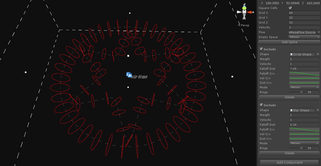
Also in the inspector you can change the velocity strength along the length of the spline as well alter the falloff distance along the length as well, this gives you complete control over what kind of contribution the spline will make to the final flow field. The velocity value sets the flow speed for the spline, this is modulated by the velocity curve. The weight value is used to calculate this splines final contribution to the flow field, for example you may have 4 splines in list, if each has the same weight of 1 then they will all contribute equally to the final flow. If you set one of them to a weight of 0.5 then that spline will have its contribution reduced by half, this makes it easy to fine tune the flow field.
Now we have a spline selected we can move on to define the the size of the flow field we are going to create, you can adjust the size either with the Size value in the inspector or you can click and drag the small white boxes on each side of the bounds gizmo in the scene. You should make the size of the flow big enough to at least enclose the splines used to make the flow field, and ideally you will make it quite a bit bigger to anything controlled by this flow has time to react to the flow outside of the splines actual area. If you find your controlled objects not being controlled enough by the flow field you make try increasing the size for the field. You can now also set the size of the flow cells to be made using the GridX/Y/Z values, the dashed lines of the gizmo will show you the current cell size, the smaller the size of the cell the finer the control of your objects will be but also the more memory the flow field will take up, so find a nice balance, ideally you will use as large a cell size as you can to get the look and feel you need. MegaFlow supports non square cells so if you have a flow that is long and thin then it may be an idea to reduce the number of cells across the flow to save memory.
Once you have that done you are ready to create the flow field. Make sure you have the MegaFlow source you want to add the final flow field to selected in the Flow section of the inspector and then click the ‘Create Flow’ button, a progress bar will appear showing the progress of the flow creation, depending on how many splines you have in your field and the number of cells in the field this can take a few seconds. Once completed the flow field will have been added as a new frame to the flow source, so if you now select the flow source and change the Frame slider you will see the final flow field, you can now test that out to control your particle system or other objects.

MegaShapes Lite
We have included a lite version of our MegaShapes system with MegaFlow to allow you to build the splines. MegaShapes is an advanced Bezier Spline solution for Unity allowing for any number of splines to be created and even animated and we have exporters available for Max and Maya to allow you to edit your splines in those 3d packages and then import them into MegaShapes. The lite version of MegaShapes also comes with components to attach objects to splines and move them along as well as various options to turn the splines into meshes, either by filling in the shapes or extruding along their length to make pipes, tubes, ribbons etc.
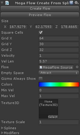
MegaFlow Create From Splines Params
Create Flow
Once you have your options set you can generate the flow field by clicking this button, the resulting flow field will be added as a new frame the selected MegaFlow source set in the Flow param below.
Preview Flow
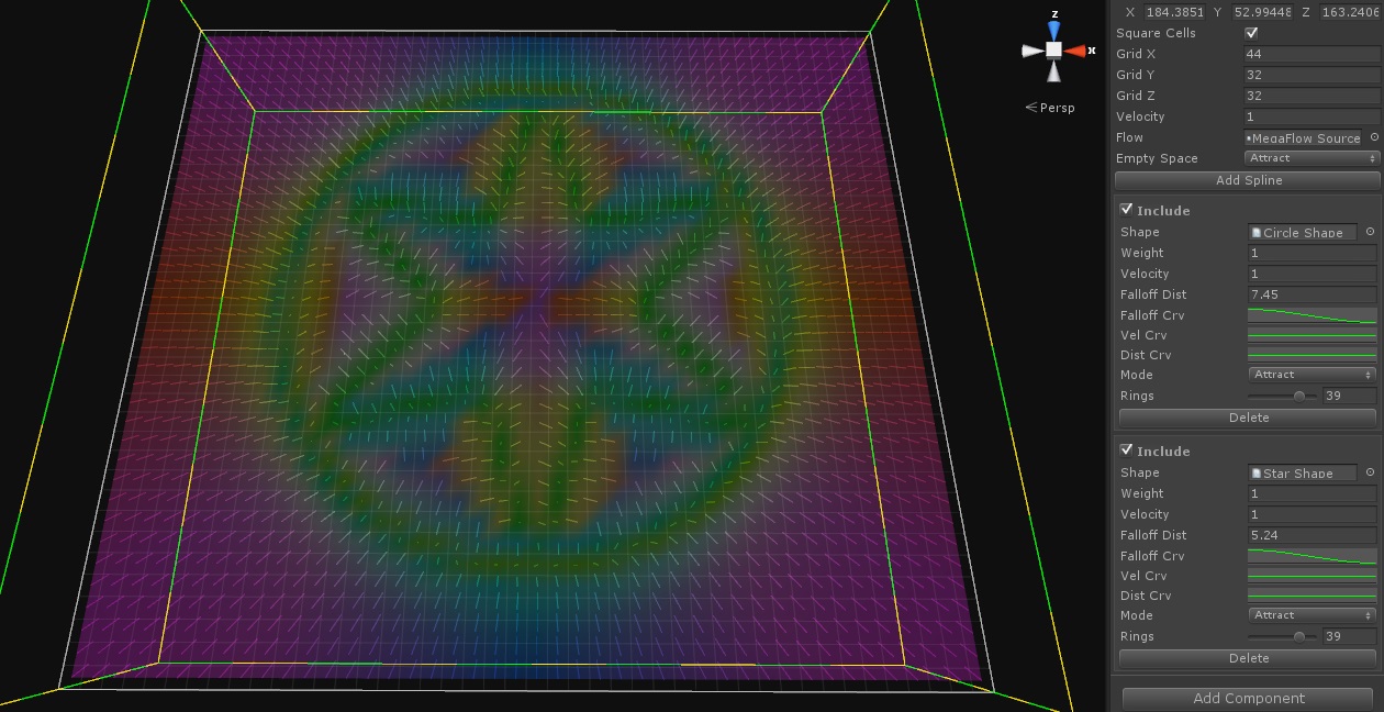
If you click this button the system will generate a preview of the flow field for you. If a preview is present a new section will appear in the inspector which will allow you to change how the data is displayed. See below.
Clear Preview Flow
When you longer need the preview click this button to delete it.
Size
The overall size of the flow field, you can also use the boxes on the side of the bounding gizmo to adjust the size of the flow field.
Square Cells
Check this box to tell the system to keep the flow cells square.
Grid X
The number of flow cells to use along the x axis.
Grid Y
The number of flow cells to use along the y axis.
Grid Z
The number of flow cells to use along the z axis.
Velocity
The global velocity value for the flow field, each splines velocity value will be multiplied by this, this makes it easy to adjust the whole flow fields velocity.
Vel Len
The length of the velocity vector arrows.
Flow
The MegaFlow source the flow field will be added to when it is created.
Empty Space
What happens in any cell that has no influence from any spline, you can say whether the flow should be towards the nearest spline, away from or flow along the spline. Attract usually works best in most cases.
Gizmo Always Show
Click this to keep the flow gizmos visible when the creat flow object is not selected.
Colors
Opens the Gradient editor where you can change the colors used to display the velocity vectors and ring gizmos.
Min Vel
The starting velocity for the color gradient.
Max Vel
The end velocity for the color gradient.
Texture3D
You can select a Texture3D as an input into the creation process, this could either be an asset in you scene created from another program or one created from a MegaFlow Source.
Texture Scale
How much the Texture3d will contribute to the flow field.
Data Display Params
If a preview of the scene has been created this foldout will appear which contains the data display options for the flow field. See below.
Splines
Opens the spline selction section. See below.
Modifiers
Opens the Modifier creation params. See below.
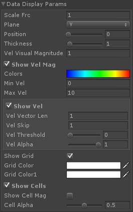
Data Display Params
This section has the main data visualization options.
Scale Frc
This allows you to scale the force of Vector field values, this will alter the coloring of the vector and cells, and alters the flow of the ribbon simulation. It will also effect any system using this fluid source to control objects, so acts as a global adjustment for the force of the fluid sim.
Gizmo Always On
It can be useful to have the fluid data visible when editing other objects in the scene, check this box to keep the gizmos being displayed for the fluid source even when it is not selected.
Plane
When visualizing the data you can choose which plane the data should be shown on, select X, Y or Z as you need.
Position
This value controls the slice of the fluid data to show, there is also a small green sphere gizmo in the scene which you can drag to change the slice being displayed.
Thickness
You can ask the system to display more than one slice of data if you want. Careful as it can get a little slow for dense fluid grids with many slices being displayed.
Vel Visual Magnitude
You can adjust velocity scaling used by just the visualization by adjusting this value, this can be useful for showing a more detail in some cases.
Show Vel Mag
If the system is displaying the velocity velocities you can either have them displayed with the colors showing the direction or showing the magnitude, if this option is checked then the magnitude of the velocity will be shown by its color. The gradient to use is set below.
Colors
The color gradient to use to display the magnitude of the velocity, clicking the box will open the gradient editor where you can set any colors you like.
Min Vel
The velocity to use for the start of the gradient.
Max Vel
The velocity to use for the end of the graient.
Show Vel
Check this to display the velocity values as lines.
Vel Vector Len
You can later the length of the vector lines used to display the velocity here.
Vel Skip
Changing this value will cause values to be skipped when being displayed, use this if the scene gets to cluttered or slow dows too much from all the lines being drawn.
Vel Threshold
You can ask the system to only display velocities above this value.
Vel Alpha
How transparent the lines are used to display the velocities.
Show Grid
Show a grid showing the size of the cells for the fluid data, the color of the grid can be changed below.
Grid Color
The first color used for the grid.
Grid Color1
The second color used for the grid.
Show Cells
Check this to show the velocities as colored cells, this only works for users of Unity Pro.
Show Cells Mag
Check this to show the velocity magnitude of the cell, will use the colors set above.
Cell Alpha
How see through the cells are.

Spline Params
This section shows the options to add and remove splines and the params for each spline. As a new spline is added a new foldout section will be added which contains the params for the spline, click the foldout to show the params.
Add Spline
Click this to add a new spline to the list.
Spline Name
A foldout button with the spline name which will open or close the params for that spline.
Include
This allows you to quickly removed a spline from the final calculation.
Shape
The MegaShape spline to use . If the shape has multiple splines attached then all the splines will used.
Weight
How much this spline will contribute to the end result.
Velocity
The velocity of the flow along this spline.
Falloff Dist
The max distance from the spline to be effected by the flow.
Falloff Crv
The curve that defines how the velocity changes over the fall off distance.
Vel Crv
This curve changes the velocity value along the length of the spline, this allows you to have fast and slow sections on the same spline.
Dist Crv
This curve changes the fall off distance along the length of the spline.
Mode
What kind of flow the spline causes, either attract, repulse or flow. Attract will move objects in towards the spline line, repulse will push objects away, flow will make things move in the direction of the spline.
Rings
This changes how many rings are used to show the area of effect of the spline.
Rings Alpha
How see through the rings are for this spline in the scene.
Delete
Delete the spline from the list.
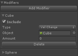
Modifier Params
You can add objects to the flow creation which can be used to modify the flow velocity in different ways, when a new modifier is added a foldout will be added in this section, click the foldout to show the options for that modifier.
Add Modifier
Click to add a new modifier to the list.
Modifier Foldout
A foldout with the name of the object used, click to open the params.
Include
Whether or not to include the modifier.
Type
The type of modifier, currently only ‘Vel Change’ is availble, this will directly effect the velocity for any cell inside the object in the scene, so if the amount is set to 0 then it will multiply any velocity value in the grid that inside the selected object by 0 so clearing that velocity, you can use this to directly alter the velocity for any area in the flow field.
Object
The object to use to define the area of influence of this modifier. Needs a collider attached.
Amount
The effect the modifier has.
Delete
Delete the modifier from the list.
Video
This video shows the Create Flow from spline system being used to create a flow field which is then used to control a particle system.


