
MegaFlow Source
The MegaFlowSource component is the core of the MegaFlow system, this is where you can import and visualize your flow data. You can import various file formats and currently MegaFlow supports .FGA, .FXD and .FLW files. FGA files are used by the Unreal Engine for controlling its particle system and you can find on the internet various plugins for packages such as Maya and 3ds Max for exporting fluid data to FGA files. FXD files are generated by FumeFX with other Fluid Simulation packages also supporting the format. FLW files are a custom human readable format for MegaFlow and we have a custom exporter for the Maya package to allow you to export the Fluid Simulation data to FLW files.
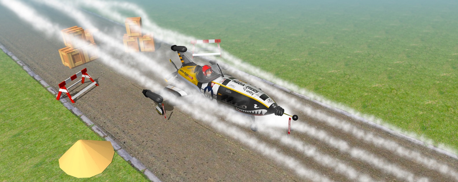
Once a fluid source has been created you can freely move, rotate or translate that object in your scene for more fun effects, for example attach one to the back of a plane object as it flies through smoke particles and see the smoke react with flow over the plane, of if you have flow in the shape of a tornado you can rotate, move and scale that flow and adjust the force scale to add more variety or menace to that tornado in your scene.
Adding a Flow Source to your Scene
To add a Flow Source to your scene just go to the GameObject/Create Other menu and select the MegaFlow section then click the Source option. This will create an object in your game called ‘MegaFlow Source’. Once added you will see the inspector params that are described below. Next you will need to import some flow data. First select the Data Source type in the drop-down. You can choose either FumeFX, MegaFlow or FGA. You can either import a single frame of data or a sequence of frames if you want to have a complex animated flow. If you select Sequence you can then set the First and Last frame from a sequence to load as well as setting a Frame Step value, this allows you to skip frames from the sequence when importing the data. Since fluid sims are quite well fluid you can usually get away with having large steps in your animation sequence, so it is a trade off between memory and accuracy. Next click the Load button, if loading a sequence you only need to pick any file from the sequence and MegaFlow will compute the correct names for the files to be loaded from that, if you are loading a single frame then pick the actual file you wish to import. A progress bar will show the progress of the import. You can cancel the import process if required.
Fluid Data Visualization
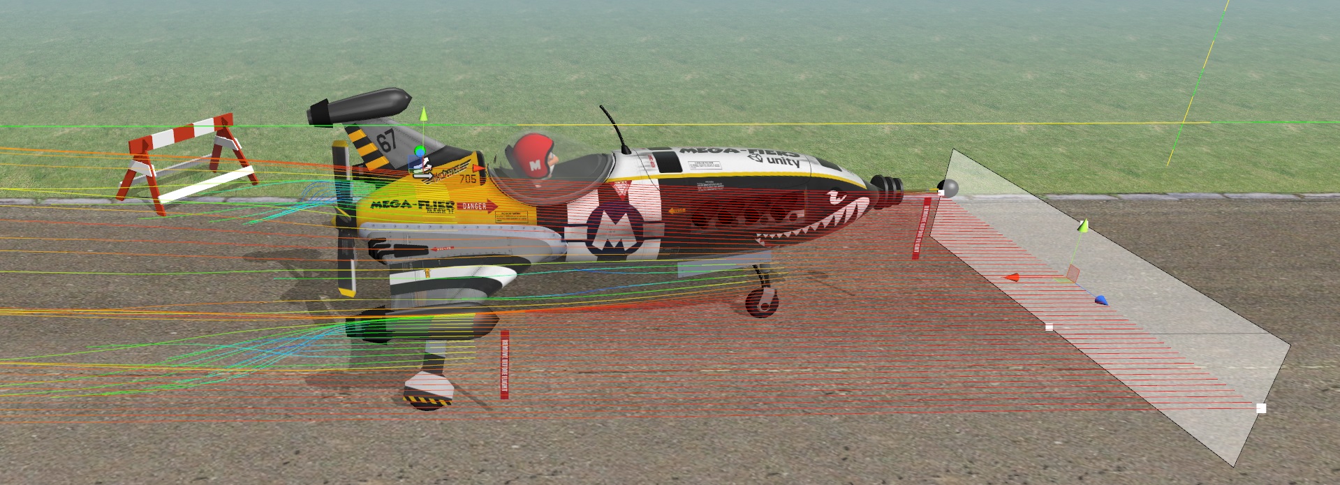
Once some data has been loaded you can then pick from the various options for displaying the data, you can choose to display the data either as vector lines, or colored cells, or a set of ribbons to show the flow of objects through the data. If you have multiple frames of data loaded you can change the one being displayed by changing the ‘Frame’ slider. Also the inspector will display the current memory usage of all the data currently loaded. The Clear All frames button will delete all the fluid data loaded to the source, or you can delete the current working frame using the ‘Delete Frame’ button.
Ribbons Option Showing the Flow Movement
Velocity Vectors

Velocity Cells and Vectors

Once you have your data loaded you can then use that to control objects in your scene, please look at the other pages for how to use the Flow Source to control your particle system, rigid bodies or general objects.
Param Guide
Below is a breakdown of each section of the MegaFlow Source inspector with an explanation for every param.

Main Params
These are the main import params for the source as well as the fold outs for the data visualization options for the fluid data.
Optimize Frame Data
Since Fluid data is usually a 3D grid of values it can sometimes take up a large amount of memory. MegaFlow allows you to optimize the size of the data to reduce it by 66% at the cost of a tiny bit of accuracy and slightly slower physics updates for objects using that frame data. If you think a frame of data could benefit from being optimized then make sure you have the frame you want selected via the Frame slider, then click this button. Once a frame is optimized it cant be undone, and if you need to revert then you will need to import the data again.
Clear All Frames
Clicking this button will delete all Fluid Data from the source.
Data Source
You can select the type of Fluid Data to import here. You can choose from FumeFX (.fxd files), MegaFlow (.flow files) or FGA files.
Sequence
You can choose to load either a single frame or a sequence of files. If you want to load a sequence then select this option. When loading a sequence MegaFlow will derive the names of the files from the one you select when you click the load button, replacing the frame number in the filename, so you only need to select any file from the sequence when asked to select a file.
First Frame
When importing a sequence you can set the first frame to load here.
Last Frame
When importing a sequence you can set the last frame to load here.
Frame Step
Usually you dont want to import every frame of a fluid simulation sequence, so you can ask MegaFlow to skip frames, so if you have a sequence that is 100 frames long but only want 4 frames, set the first frame to 0, last frame to 100 and frame step to 25, then MegaFlow will only import frame 0, 25, 50 and 75
Load Button
Click this button to load your file or sequence, you will be presented with a file select window, for a single frame import select the actual file you want to import, for a sequence you only need to select any frame from the sequence.
Info Panel
This panel gives a breakdown on the current number of frames imported, the total memory use and the current frame memory use, it will also say if the frame data is optimized or not.
Frame
If you have more than frame of data imported the Frame slider will appear, this allows you to select which frame of data should be visualized.
Normalize Frame
This button will normalize the velocities of the current frame. This can useful if the maximum velocity is not known for a frame then the frame can be normalized and then the overall velocity controlled by the scale value to a known value. This is also required by the moving source system so the system can correct the flow field velocity for the velocity of the moving object, so before using a frame with the moving source system it should be normalized.
Delete Frame
Click this button to Delete the current frame of data.
Frame Offset
If you are importing more than frame of data to a source it maybe those frame have different grid values or sizes so you can use the offest value here to position the frame in the source as required.
Data Display Params
Click to open the main data display options. See below.
Ribbon Params
Click this to open the Ribbon display params. See below.
Texture Options
Click this to open the Texture3D creation options. See below.
Advanced Options
Click this to open the Advanced Options. See below.

Display Params
This section has the main data visualization options.
Scale Frc
This allows you to scale the force of Vector field values, this will alter the coloring of the vector and cells, and alters the flow of the ribbon simulation. It will also effect any system using this fluid source to control objects, so acts as a global adjustment for the force of the fluid sim.
Gizmo Always On
It can be useful to have the fluid data visible when editing other objects in the scene, check this box to keep the gizmos being displayed for the fluid source even when it is not selected.
Plane
When visualizing the data you can choose which plane the data should be shown on, select X, Y or Z as you need.
Position
This value controls the slice of the fluid data to show, there is also a small green sphere gizmo in the scene which you can drag to change the slice being displayed.
Thickness
You can ask the system to display more than one slice of data if you want. Careful as it can get a little slow for dense fluid grids with many slices being displayed.
Vel Visual Magnitude
You can adjust velocity scaling used by just the visualization by adjusting this value, this can be useful for showing a more detail in some cases.
Show Vel Mag
If the system is displaying the velocity velocities you can either have them displayed with the colors showing the direction or showing the magnitude, if this option is checked then the magnitude of the velocity will be shown by its color. The gradient to use is set below.
Colors
The color gradient to use to display the magnitude of the velocity, clicking the box will open the gradient editor where you can set any colors you like.
Min Vel
The velocity to use for the start of the gradient.
Max Vel
The velocity to use for the end of the graient.
Show Vel
Check this to display the velocity values as lines.
Vel Vector Len
You can later the length of the vector lines used to display the velocity here.
Vel Skip
Changing this value will cause values to be skipped when being displayed, use this if the scene gets to cluttered or slow dows too much from all the lines being drawn.
Vel Threshold
You can ask the system to only display velocities above this value.
Vel Alpha
How transparent the lines are used to display the velocities.
Show Grid
Show a grid showing the size of the cells for the fluid data, the color of the grid can be changed below.
Grid Color
The first color used for the grid.
Grid Color1
The second color used for the grid.
Show Cells
Check this to show the velocities as colored cells, this only works for users of Unity Pro.
Show Cells Mag
Check this to show the velocity magnitude of the cell, will use the colors set above.
Cell Alpha
How see through the cells are.
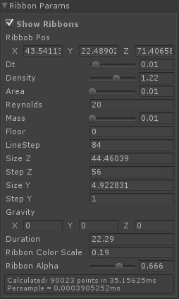
Ribbon Params
MegaFlow allows you to send ribbons into the flow data to visualize how an object or a particle will react to the flow. Each ribbon will render a coloured trail so you can see how it will react, you can alter the physics params used to control the flow of the ribbon as well as how many ribbons are sent and the size of the area they are sent from. When enabled you will see an extra position handle appear in the scene which you can use to move the ribbon source around, you can also scale the ribbon source in the scene by clicking and dragging the small squares on the edge.
Show Ribbons
Turn on the display and calculation of the ribbons. Depending on the settings below the ribbon display can be quite slow.
Ribbon Pos
The start position for the ribbons in the flow. You can also change this by dragging the position handle in the scene view.
Dt
The time step to be used by the physics calculation.
Density
The density of the fluid the ribbons are flowing through.
Area
The surface area of the object being simulated, the larger the area the more influence the flow will have over the object.
Reynolds
The Reynolds number for the fluid, you probably wont need to change this.
Mass
The mass of the object being simulated, the lower the mass the more influence the fluid flow will have on the ribbon.
Floor
A floor value to stop ribbons.
LineStep
The distance between samples when drawing the ribbon paths, higher values means less lines are drawn and is faster.
Size Z
The size of the ribbon source in the Z direction.
Step Z
How many ribbons along the Z axis.
Size Y
The size of the ribbon source in the X direction.
Step Y
How many ribbons along the y axis.
Gravity
Gravity value to be used by the physics.
Duration
How long the object exists for the physics simulation, basically how long a trail is shown.
Ribbon Color Scale
Adjust the velocity value scaling when calculating the color. The color shows the velocity of the object at a point on the trail.
Ribbon Alpha
How see through the ribbons are.
Info Panel
This panel gives a little info on how many physics calculations were done to compute the ribbons, how long that took, and the average time per physics step.
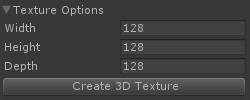
Texture Params
This describes the params for the Texture Options inspector.
Width
The width of the texture to create, This will be changed to the nearest power of two.
Height
The height of the texture to create, This will be changed to the nearest power of two.
Depth
The depth of the texture to create, This will be changed to the nearest power of two.
Create 3D Texture
Clicking this button will create a new Texture3D asset in your project in a folder called ‘MegaFlow Textures’ This texture can then be used by other systems that use 3d tetxures or can be used as an input in the Create Flow System.

Advanced Params
This describes the params for the Advanced Options inspector.
New Grid Size
The number of grid cells along each axis the new flow frame will have.
Resample Grid
When this button is clicked the current flow frame will be re sampled to a new grid of the size set above and added as a new frame to the source. This can be useful for reducing the memory use of a frame of data and testing that without having to recreate the flow data in your fluid dynamics software etc.
Videos
Video showing the output of a Maya Fluid Simulation exported via the MegaFlow exporter and used to control a particle system showing smoke flowing around the MegaFlier and other obstacles.

Another video showing a FumeFX simulation generated in 3ds Max and exported to FXD files used to control the movement of 1000’s of objects. No collision detection or Rigid Body physics is used in the scene, all movement is controlled by MegaFlow.


