

This system makes it easy to lay out a series of way points and then have the system automatically place poles along the path and then string wires between those poles for you. You are free to select any pole type to use and then adjust material and physics settings, spacing and variations. You can add, delete and move any way points at any time and the poles and wires will update for you. This makes it very easy to lay out your wires along side existing roads or rail lines etc. that may be in your scene. The system can also be told to snap the poles to any underlying surfaces and align the poles to that surface or make them upright.
When you create a Pole Planter object the system will 4 way points for you in a line to get you started, you can then drag those points around using the position handles. When you move the mouse pointer to near the centre of a way point line a green square will appear half way along the line, if youl hold down the ‘A’ key and then click the green point a new way point will be added at that point for you.
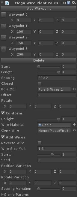
Plant Poles Params
Add Waypoint
Click this button to add a new waypoint to the end of the current path.
Waypoint List
This shows the positions of the current way points in the path.
Delete
Delete the last point in the list, alternatively by the side of each way point there is a small button which can be used to delete that particular way point.
Start
When you create the poles along your path you do not have to have them start at the beginning of the path use this value to move the start point along the path.
Length
You can also use a portion of the path by setting this value to less than one.
Spacing
This value controls the approximate distance between each pole when it is placed on the path.
Closed
You may want your path to form a closed loop, if so check this box and the path will be closed for you and any wires added will also form a complete loop.
Pole Obj
This is where you select the pole type to use for this set of poles, you should select a pole prefab that has had the wire connection points already defined. If you select a pole object that has no connections then no wires will be created when you click the Add Wires check box, but you can still use that object and then add the connection points later in the Mega Wire inspector.
Offset
You can ask the system to plant the poles offset to one side or the other of the path, so for example you may have laid your path along the centre line of a road, you can then use the offset value to have the poles planted a set distance either side of the path so lining the side of the road.
Rotate
The system will plant the poles at right angles to the direction of the path, for some pole types this may not be the correct orientation, in that case you can alter the rotation used by changing this value.
Conform
Checking this button will ask the system to snap the poles to any surface that is underneath the pole, this could be a terrain or a series of mesh colliders
Upright
If the poles are told to conform to the surface they are over the poles will by default point vertically up from the surface, this maybe what you want but you may want the poles to point perfectly up, if so you can use this slider to say how vertical you want the poles to be.
Wire Material
This is where you select the material to be applied to any wires that are created for the planted poles.
Copy Wire
If you already have a MegaWires object in your scene with the various params set just the way you want them then you can pick that object here and the settings from that wire will be copied to the new one for you.
Add Wires
Click this box to have the system build the wire objects for you.
Reverse Wire
Sometimes you may require the poles to be created in the other direction, for example some poles at in and out connections in different places, and depending on the way your path is built they may be added around the wrong way by default you can use the rotate value to fix this or just click the reverse wire box to have pole planted from the other end.
Wire Size Mult
When the wires are built they will use the radius values defined in the connection points, you can though easily increase or decrease that size by changing this value, this is useful if you are creating wires that are quite far from the camera and where they wires may be too thin to be seen clearly, you can increase the size to make them stand out a little better.
Stretch
If you wires are created too droopy or too stiff you can adjust that by changing the pre stretch value, a smaller value here will mean the wires have been pulled tighter when they are hung, a larger value means they were hung with a little slackness.
Seed
When using the variation values below the random seed value here is used, you can change this value to get a different set of variations until you get one you are happy with.
Position Variation
The system can be asked to vary the positioning of the poles from their intended position by the values here.
Rotate Variation
The system can be asked to vary the rotation of the poles from their intended rotation by the values here, this is useful for adding a more rustic look to your poles instead of them all being perfectly upright.
Spacing Variation
You can also vary the spacing between your poles.
Gizmo Params
Click this to open the various params that control the display of the planting gizmos.
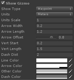
Gizmo Params
These params control how the gizmos for way points are displayed.
Show Gizmo
Click this to have the waypoints or pole spacing gizmos displayed.
Show Type
You can ask the system to either show you the way points for the path, or the pole spacing distances, or both. Select the one you need.
Units
You can select the units the distances are displayed in here, by default the distances are displayed in meters with one unity unit equalling 1m, you can change the scale below.
Units Scale
By default the distances are display with 1 Unity unit equalling 1m, you can change that ratio here if your scene works of a different scaling.
Arrow Width
You can control the width of the various measurement arrow heads with this value.
Arrow Length
You can control the length various measurement arrow heads with this value.
Arrow Offset
How far the measurement arrows are display from the points they measure.
Vert Start
The measurement vertical line distance from the actual line.
Vert Length
The max length of the vertical measuring line.
Dash Dist
The length of the dash on the measurement lines.
Line Color
The color of the main lines.
Arrow Color
The color of the arrows.
Other Color
Color of the vertical measurement lines.
Dash Color
The second dash color.
Plant Poles Video

You must be logged in to post a comment.


