

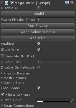
This is the core component of the MegaWires system and contains all the params to control the physics, the mesh building and the behaviour of the wire in the scene. This component has a lot of options but most of them can be left on the default values so it is not that daunting. This component would have been added to your scene for you either when you used the Pole Planting system, or when you created a wire with the MegaWire Window.
Mega Wire Params
Disable All
This will turn off all the updates to all the wires in the scene.
Rebuild
If you have made any changes to the params below clicking this button will rebuild the wire with those new settings.
Warm Physics Time
When you create a wire it may not be in the rest state so when you run your scene the wire will fall into place, if you don’t want this to happen you can use the Run Physics button below, this will run the physics simualtion on the wire for the length of time defined here, so depending on how your wire is setup you can increase or decrease this value so that wire is in a settled state when you run your scene.
Run Physics
Click this button to run the physics on the wire for the period of time above.
Open Select Window
Clicking this button will open the helper window where you can re select the poles to use for the wire from the scene. There is a separate help page on the Select Window (link to go here) – Currently this is disabled.
Add Wire
This will add a new wire to the simulation, you can change its settings in the connection section that is described below.
Enabled
You can disable each wire in your scene with this value.
Show Wire
This will turn the mesh for the wire on and off.
Disable on Dist
The wire system has a system built in where you can have it turn of the physics and mesh update for each span based on the distance from the camera. If you check this you will see some grey transparent spheres appear centred on the mid point of each wire span. The size is controlled by the disable dist value below, if on the wire update will turned off if the camera is outside the sphere and turned back on if the camera gets close enough. Note if you move a pole in the scene while the system is running and the span is disabled due to distance it will automatically be woken up so that the wires will react to the movement of the pole.
Disable Dist
The distance from the camera beyond which the wire update will be disabled.
Disable on InVisible
You can also have the system turn off the wire updates if a span stops becoming visible to the camera.
Physics Params
Clicking this will open up the params that describe the physics simulation of the wire.
Mesh Params
Clicking this will open up the params that describe how the wire is turned into a mesh.
Connections
Clicking this will show you the connections for the poles that are used, you can tweak the values and delete connections that are no longer required.
Hide Spans
Clicking this will hide the span objects in the hierarchy so helping keeping your project hierarchy a little cleaner.
Show Gizmos
Click this to show the masses used to build your wires along with the springs that connect those masses.
Gizmo Color
The color of the spheres that show the disable on distance value.
Span Connections
Click this to show the connections params for all the wires in the object, by un checking the boxes you can have wires detach and attach themselves from the pole connection points.
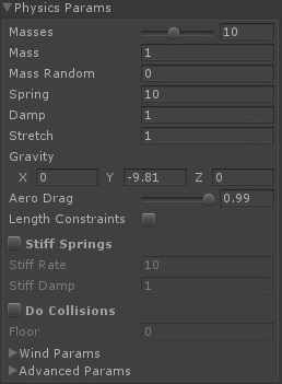
Physics Params
These values control the physics simulation used to model the wires. Some of these values can cause the physics to explode, if that happens just changed the value back and hit the Rebuild Physics button above. Most of the time the default values should serve you well.
Masses
How many masses the simulation will use to simulate each wire, the more masses you have the more accurate the simulation will but will also use more CPU time (though not a lot) you can get convincing simulations with 3 masses so it is up to you as to what you need, just play with the value until you are happy.
Mass
The total mass for each wire, the lighter the wire the more easily it will be effected by wind and gravity, you should change this value to reflect the size of the wire and length and the material it is made off, but again tweak until you get a look you are happy with.
Mass Random
If this value i snot 0 then a random amount between +- the value set here will be added to the masses, this will help to stop each wire looking and behaving exactly like its neighbours, so wires with random mass will hang slightly differently etc.
Spring
The spring rate for the springs that connect the masses, increase this to make the wire stiffer, this value can cause the system to explode depending on the damp rate, the mass and the time step of the system. Reset the value and click Rebuild Physics if the system goes wonky.
Damp
The damping rate for the connecting springs, this along with the spring rate above control the amount of stretch for a given force on the wire.
Stretch
This value adds a pre stretch value to the wire, this is an easy way to make the wire sag less for a given spring rate or you can make a wire longer than the span so it will fall on to the floor.
Gravity
The gravity value used by the physics, you should not need to change this.
Aero Drag
This value controls how quickly the wire masses will slow down due to movement through the air, if you find your wires are a bit to twitchy you can reduce this a little.
Length Constraints
This will add extra constraints to the system to make the wires very stiff.
Stiff Springs
If you dont need super stiff wires you can add in extra stiffness springs, this will make the system act more like a metal cable as opposed to a rope.
Stiff Rate
The spring rate for the stiffness springs.
Stiff Damp
The damping rate for the stiffness springs.
Do Collisions
The system has a very simple collision system where you can define a floor height value, with this option checked the system will do collisions with that floor value for you.
Floor
The height of the floor to use in the collisions check.
Wind Params
This will open up the wind params. Described below.
Advanced Params
This will open up the advanced options params. Described below.

Wind Params
These params control how the wires interact with any wind.
Wind Src
The wire can either be effected by the global wind strength and direction values or you can choose a Wind object that will effect your wire. The wind object gives a better control over the wind with turbulence and noise values. If no object is selected here then the global wind values will be used.
Wind Dir
The global wind direction.
Wind Frc
The global wind strength.
Wind Effect
This value can be used to reduce or increase the effect of any wind on your wire, so if your wire is in a more sheltered area you can reduce this value, or if your wire is higher up on a hill you can increase this value.
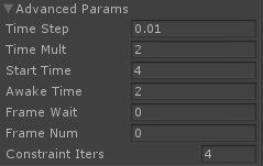
Advanced Params
These value control some of the finer points of the physics system as well as providing more options to increase the performance of multiple wires in a complex scene.
Time Step
The time step used by the physics system to simulate the wires. The larger this value the less CPU time the system will take but it can also cause the system to go wrong depending on the spring, mass and damping rates used. When you have your wires working you can try increasing this value little by little to the highest value you can before the system messes up to get the best performance you can from the system.
Time Mult
Depending on wht you need from the simulation your wires may be updating too fast or too slow in your scene for your liking, you can control the look and feel of the simulation by changing this value, increasing this value will changes to happen quicker making the wires seem lighter etc. Decreasing the value will make the wires seem heavier. Lower values will reduce the CPU use of the physics simulation.
Start Time
If you have Disable on Distance system enabled then when you scene starts distant wires may not update depending on their distance from the camera, if this value is non zero then the wires will be woken up for this length of time from the scene starting so they can settle into place etc. You can also just use the ‘Run Physics’ option above to get your wires into a pre warmed state.
Awake Time
If you have the wires being disable on distance from the camera they will still be woken up if a pole they are connected to is moved in the scene, this value says how long the wires will stay active after they have been woken in that way.
Frame Wait
If you have a lot of wires in your scene you can stagger the updates over set frames, if this value is non zero then the system will wait that number of game frames before it will update the system. So a value of 4 will mean the system is updated only every 4th frame. This will slow the look of the simulation down as it is only being updated 1 frame in 4, you can counter this by setting the Time Mult value above to 4 top compensate.
Frame Num
If you are using the frame wait option, you can set this value to control which frame the wire will update on, so for example if you have 3 MegaWire objects in your scene you can set Frame Wait on each to 3 and the set the Frame Num to 0, 1 and 2 on the 3 wires, then only one wire will be updated on any frame.
Constraint Iters
This determines how may times the constraints are calculated per frame, if you are not using Length Constraints then this value has little effect, again the lower the value the less CPU time the system will use.

Mesh Params
These values control how the wire simulation is turned into a mesh that is displayed in your scene.
Material
The material to use for the wires.
Sides
How many sides the wire mesh will have. The higher the value the smoother the rope will look up close, but most of the time your wires will only need a very low value here, 4 is a good general value for wires you move close to, if your wire are in the distance or your scene is 2D then setting this to 2 will make flat wires but will still look good in most situations.
Segments
This is how many segments the wire has been split into, this value is calculated from the Segs Per Unit value below.
Segs Per Unit
This controls how many segments a wire mesh will have, this is a per unit length of the wire, so if a value of 1 is used then the mesh will have vertices every 1 unit of its length so if the wire is 15 units long it will have 15 divisions. Adjust this value to get a look you are happy with, it will depend on how close you will be to your wires in the scene as well as how many masses you have used for your wires. The system by default uses a cubic interpolation between masses so it will try and generate a nice curve for you.
Strands
You can elect to have the system build multi stranded twisted wires if you need that, this value says how many strands the wire will be built from.
Offset
If you have more than one strand you can select how far apart they are placed.
Strand Radius
The radius of each strand making up the wire.
Twist
How much the multistranded wire is being twisted along its length.
Twist Per Unit
This defines how many degrees of twist are applied to multi stranded wires per unit length.
Gen UV
Says whether UV coords are generated, you may not need uv mapping if your wires are quite a way in the distance, turning this off will speed up the meshing system a little.
UV Twist
You can ask the system to twist the uvs along the wire length, you may need this if your wire texture does not already have a twisted look to it.
UV Tile X
How often the uv is tiled in the x direction.
UV Tile Y
How often the uv is tiled in the y direction.
Linear Interp
By default the system uses cubic interpolation between the masses which gives a nice smooth curve to the wire, you may not need this so you can opt to use the faster linear interpolation instead, in most cases you will not notice much difference.
Calc Bounds
Ask the system to recalc the bounds info for the wires, if your poles are not moving much you wont need this.
Calc Tangents
If you are using a bump shader on your wires you will need to turn this on, this is quite a slow option so it is not recommended.
Vertex Count
This will show you how many vertices each span of the wire is using.

Connections
This section shows you all the wire connections the system is using, you can alter the values here and adjust wire radius values, or delete connections that are not needed any more. You can add a connection by clicking the Add Wire button at the top of the inspector.
Radius
The radius of the wire that will use this connection.
Out Offset
The location of the connection point of the wire leaving the object.
In Offset
The location of the connection point of the wire entering the object.
Delete
Delete this connection.
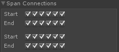
Span Connections
This sections allows you to disconnect a wire from a pole and or re connect it again. If the simulation is running and you uncheck a box the wire will fall to the ground. Checking the box again and the wire will attach itself again to the pole. There is a check box for every connection point on a pole and a section for every span in the whole wire object.
Start
Disconnect the start of the wire.
End
Disconnect the end of the wire.
Introduction to MegaWires

MegaWires Physics and Meshing basic options

Interaction and Hanging objects

You must be logged in to post a comment.


